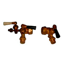
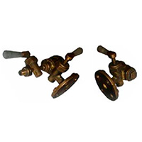
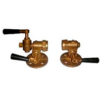
Level Indicators with Shut-Off Valves
Description of Section "Level Indicators with Shut-Off Valves"
Level Indicators with Shut-Off Valves are elements designed to monitor and visually determine the level of liquid in tanks, boilers and other vessels. They operate based on the principle of communicating vessels, where the liquid level in the level Indicator corresponds to the liquid level in the working vessel. These devices ensure system tightness, prevent leakage of the working medium, and allow for safe maintenance.
Design Type of Level Indicators with Shut-Off Valves
Design includes an upper valve (installed at the top of the vessel) and a lower valve (at the bottom of the vessel). The operating principle is based on the principle of communicating vessels. Liquid from the working vessel enters the level gauge through the shut-off device, allowing visual observation of the liquid level.
The connection type of level indicators with shut-off devices can be flanged or threaded.
Installation of Level Indicator with Shut-Off Valves
Installation is carried out in the following order:
1. Connecting the Lower Valve
- Secure the lower valve of the shut-off device to the lower part of the vessel (tank, boiler) using a flanged or threaded connection.
- Use sealing gaskets (e.g., paronite) to ensure the tightness of the connection.
- If a test-drain valve is provided, connect it to the lower valve.
2. Connecting the Upper Valve
- Secure the upper valve to the upper part of the vessel in a similar manner.
- Ensure that the center-to-center distance between the upper and lower valves matches the length of the level gauge frame.
3. Installing the Glass Frame
- Insert the glass frame into the special openings of the upper and lower housings of the shut-off device.
- Seal the ends of the tube with packing material (e.g., asbestos cord with graphite lubricant). This will prevent leakage of the working medium.
- Tighten the packing nuts evenly to avoid misalignment of the tube.


